WiFi Adapter Mod
Introduction
The greatest, by far, downgrade from the Wii to the Wii mini has got to be the removal of WiFi capabilities. While in 2011, when the Wii mini was released, this was not a big deal, as the Wii's online services were then discontinued, wifi integration today is still very useful for the console as users can still access the internet through various homebrew and use online service replacements such as Wiimmfi and RiiConnect24.
Adding WiFi to the Wii mini requires not only the Wii WiFi module, but also the addition of several passive components to the motherboard, as well as a software patch to enable the WiFi module. This guide will cover the hardware side of the mod, and the software side will be covered in the Software section. While gathering all the parts by yourself is definitely easy, webhdx has put together a ready-made kit with everything required to get the mod up and running, including the passives, wifi card and even a pair of wifi antennas.
Parts/Tools Required
- A Wii WiFi card, which can be salvaged from a broken Wii or purchased online from eBay or AliExpress.
- An assortment of smd components listed in the table below, which can be purchased from any components retailer such as Mouser, DigiKey, etc.
- Two 2.4GHz antennae with uFL connectors, which can be salvaged from another Wii or purchased online from various retailers.
- You can optionally obtain all of the above in a convenient kit put together by Webhdx, which you can purchase on his website, which can help you save time and even money, depending on where you live.
- A quality soldering iron with a fine tip
Required SMD Components:
| Designator | Value | Package (imp) | Quantity |
|---|---|---|---|
| P13 CONN | 0529910208 20-pin molex connector | N/A | 1 |
| RA20 | 4x 100Ω Resistor Array | 0402 | 1 |
| R212, R213 | 100Ω | 0402 | 2 |
| FIL50 | 1Ω | 0603 | 1 (optional) |
| C136 | 10nF 16V | 0402 | 1 |
| C138 | 11μF (10V) | 0603 | 1 |
| C139 | 100nF 16V | 0402 | 1 |
Instructions
Firstly, you will need to solder the passive components, located on both sides of the board. Solder the components in the table above to their corresponding spots on the boards marked in blue (Right-click or hold image and open in new tab to enlarge). The reference designators on the first column of the table correspond to the silkscreen markings on the board. Solder the components to the empty pads adjacent to those silkscreen markings.
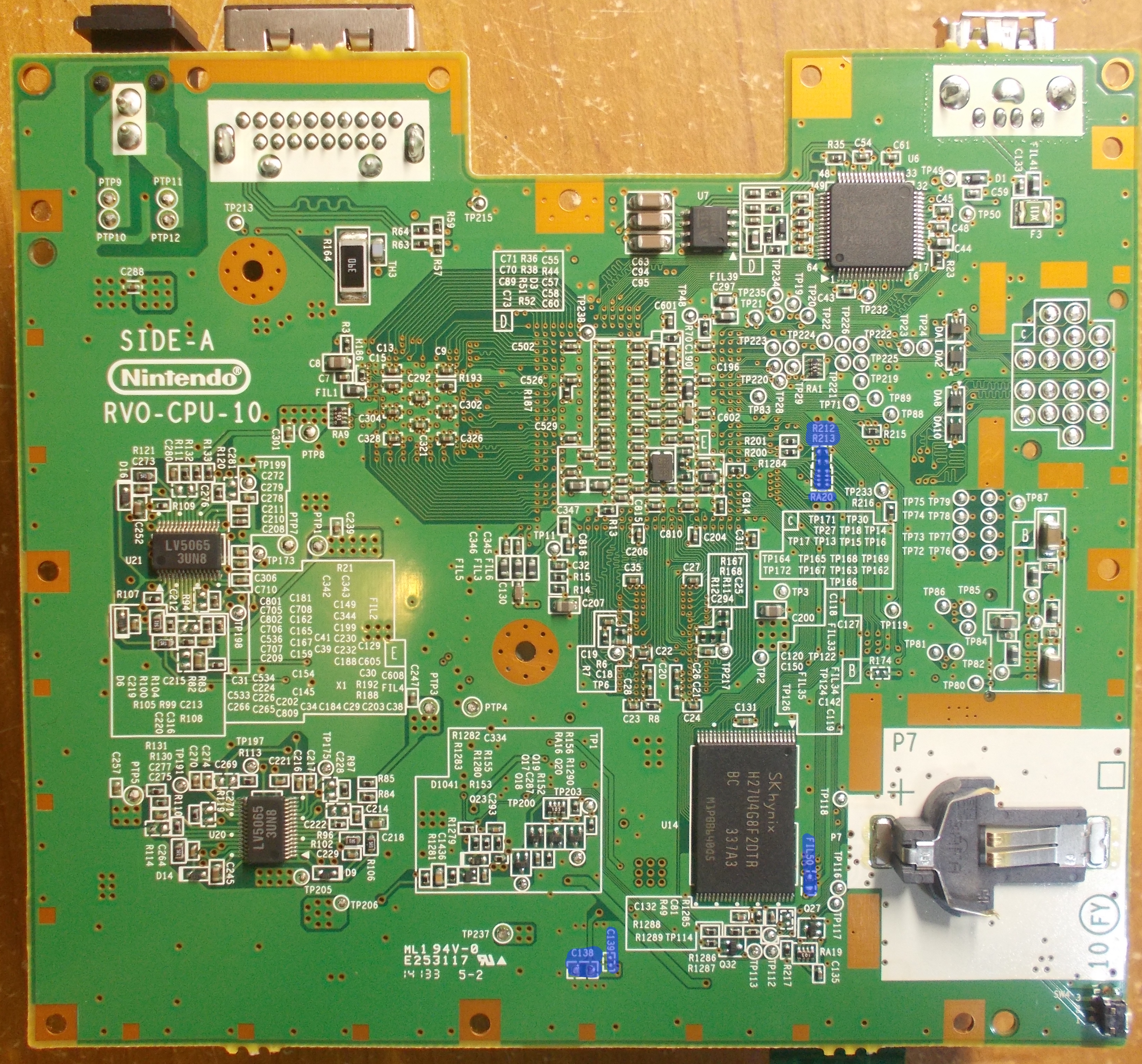
Bottom Side (Side-A):
The bottom side has most of the components other than C136 and the wifi card connector itself, which are located on the other side. Locate the pads (marked blue) on the bottom side of the board and solder the appropriate components as shown in the table above. You can use the following image as a reference:
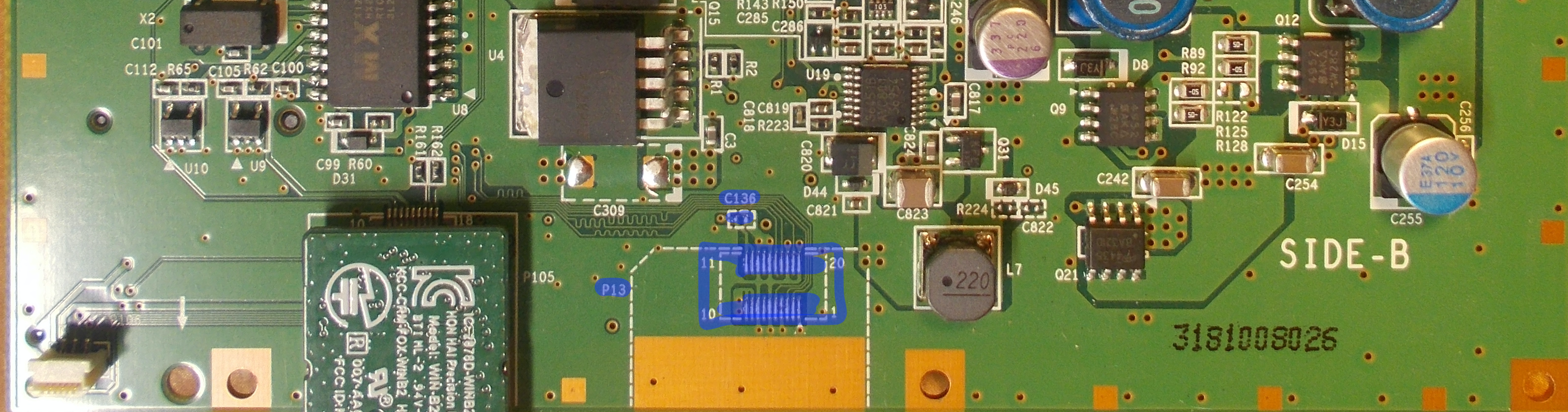
Top Side (Side-B)
You will also need to solder on C136, as well as the connector for the wifi card itself on the top side of the board. Use the following image as reference:
INFO
If your board has its test points pre-tinned with lead-free solder, it is highly recommended you wick it off before you solder the components on with your own, preferably leaded. This is because leaded solder has a lower melting point than lead-free solder, and the two do not mix well together, resulting in a brittle joint that can break easily.
Attach the wifi card to the console, extending out from the board following the silkscreen outline, just like the bluetooth card next to it.
Post-Install
INFO
If you do not have a WiFi card already installed, proceed to installing the System Menu (no WiFi card)
If you already have a WiFi card installed, you should have already re-installed the System Menu.
We'd love to see your completed mod, feel free to join us on our Discord and post a picture in #pimping-general
INFO
Return to Pick-a-Pimp | Continue to site navigation
We have other tutorials that you might like.